When the labels finally match the pins as you wire a home sensor board, you feel the relief immediately.
That is why the best Io modules for 2026 matter so much.
You need a clean fit for your voltage, space, and software.
Whether you choose an Arduino screw terminal breakout, an ESP32 board, a tiny XIAO ESP32S3, a LoRa option, a Siemens LOGO! setup, a relay expansion, or a PCF8575 expander, the real skill is knowing which module will save you trouble before it starts.
| Electronics-Salon Arduino Screw Terminal Breakout Module for UNO R3 | 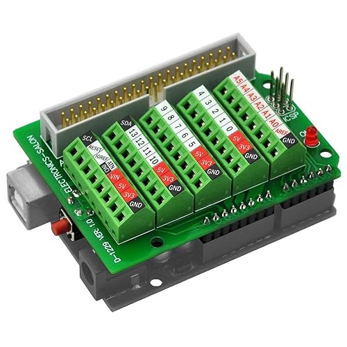 | Best for Arduino | I/O Expansion: 40-pin breakout | Voltage: Arduino UNO compatible | Form Factor: PCB module | VIEW LATEST PRICE | Read Our Analysis |
| ESP32 Development Board with CP2012 Chip 3 Pack | 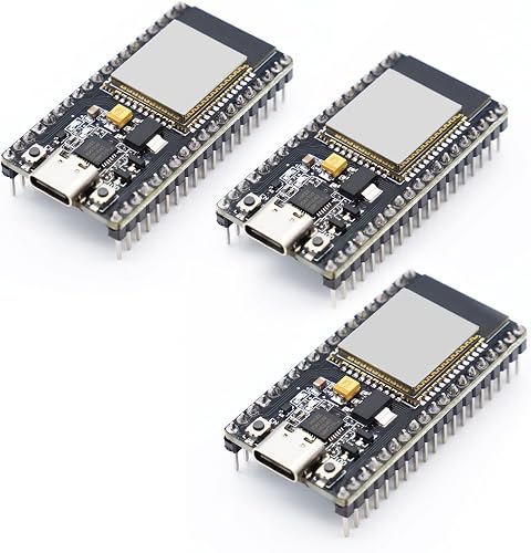 | Best Value | I/O Expansion: 32 GPIO | Voltage: 3.3V | Form Factor: Compact board | VIEW LATEST PRICE | Read Our Analysis |
| Seeed Studio XIAO ESP32S3 Wi-Fi BLE Microcontroller | 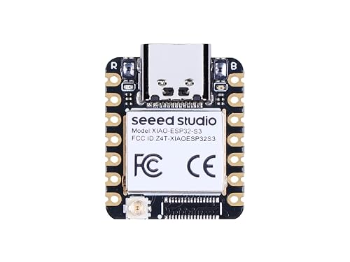 | Best Compact Pick | I/O Expansion: GPIO board | Voltage: Battery powered | Form Factor: Thumb-sized | VIEW LATEST PRICE | Read Our Analysis |
| Siemens LOGO! 12/24RCE Logic Module (6ED1052-1MD08-0BA0) | 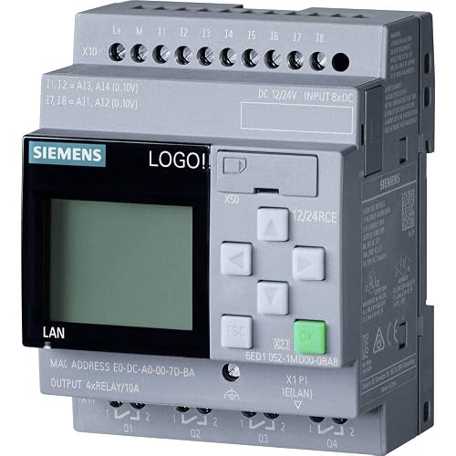 | Industrial Grade | I/O Expansion: 8 DI / 4 DO | Voltage: 24VDC | Form Factor: Logic module | VIEW LATEST PRICE | Read Our Analysis |
| ESP32 LoRa V3 Development Board with OLED Display |  | Best for IoT | I/O Expansion: Expansion-ready | Voltage: USB/battery powered | Form Factor: Development board | VIEW LATEST PRICE | Read Our Analysis |
| ACEIRMC PCF8575 I2C 16-IO Expander Board (10pcs) |  | Best IO Expansion | I/O Expansion: 16 I/O | Voltage: 2.5–5.5V | Form Factor: Expander board | VIEW LATEST PRICE | Read Our Analysis |
| Siemens stlogo Expansion Module DM8 12/24R PU/I/O 12 24V/12V/24V |  | Best for Automation | I/O Expansion: 4 I/P, 4 O/P | Voltage: 12/24V | Form Factor: Expansion module | VIEW LATEST PRICE | Read Our Analysis |
More Details on Our Top Picks
Electronics-Salon Arduino Screw Terminal Breakout Module for UNO R3
If you want a clean and reliable way to connect your Arduino UNO R3 to external components, the Electronics-Salon Arduino Screw Terminal Block Breakout Module is a smart choice. It includes a soldered FR-4 board with dual copper layers, sturdy M2 steel hardware, and 40 IDC pins for ribbon cables. The board moves Arduino pins to screw terminals with 3.5 mm pitch, so your wires remain secure. It accepts 26 AWG to 16 AWG wire, features a power LED, and provides a side reset button. The ICSP header keeps setup simple and straightforward.
- I/O Expansion:40-pin breakout
- Voltage:Arduino UNO compatible
- Form Factor:PCB module
- Connectivity:Screw/IDC
- Programming Support:Arduino-compatible
- Use Case:Prototyping
- Additional Feature:Power-on LED indicator
- Additional Feature:Side reset button
- Additional Feature:ICSP adapter header
ESP32 Development Board with CP2012 Chip 3 Pack
The ESP32 Development Board with CP2012 Chip, 3 Pack is an excellent choice if you want a compact, reliable board set that makes wireless projects easier to tackle. It features dual-core ESP32 performance at 240 MHz, plus Wi-Fi and Bluetooth 4.2 for stable connectivity. The CP2012 USB-to-serial chip enables fast communication with your computer via Type-C or Micro USB. With 4 MB flash, 4 MB RAM, and 32 GPIO pins, you can build, test, and expand with confidence. Support for Arduino IDE, MicroPython, Lua, FreeRTOS, and LWIP gives you plenty of room to grow.
- I/O Expansion:32 GPIO
- Voltage:3.3V
- Form Factor:Compact board
- Connectivity:USB, Wi‑Fi, Bluetooth
- Programming Support:Arduino IDE
- Use Case:IoT projects
- Additional Feature:Dual-core LX6 CPU
- Additional Feature:Bluetooth 4.2 support
- Additional Feature:240MHz clock speed
Seeed Studio XIAO ESP32S3 Wi-Fi BLE Microcontroller
Seeed Studio XIAO ESP32S3 Wi-Fi BLE Microcontroller fits best when you need serious wireless power in a tiny space, especially for smart home nodes, wearables, and compact robotics. You get a dual-core ESP32-S3 chip running up to 240 MHz, so your projects feel quick and responsive. It supports Arduino and MicroPython, which makes setup user friendly. It provides 2.4 GHz Wi-Fi, BLE 5.0, and a U.FL antenna connector to help you reach over 100 meters. Battery charging is included, there are four power modes, and deep sleep current is 14 μA to keep your build efficient. The thumb-sized board also fits standard breadboards.
- I/O Expansion:GPIO board
- Voltage:Battery powered
- Form Factor:Thumb-sized
- Connectivity:Wi‑Fi, BLE
- Programming Support:Arduino/MicroPython
- Use Case:Wearables
- Additional Feature:BLE 5.0 support
- Additional Feature:14μA deep sleep
- Additional Feature:Lithium battery charging
Siemens LOGO! 12/24RCE Logic Module (6ED1052-1MD08-0BA0)
12/24RCE logic module, part number 6ED1052-1MD08-0BA0, is ideal when you need a compact control unit that can handle real industrial tasks without making setup feel like a maze. It provides 8 digital inputs, 4 analog inputs, and 4 relay outputs, so you can wire sensors, buttons, and small loads with confidence. The 24V design, LCD screen, Ethernet support, and 400-block memory let you build and adjust logic quickly. Because it is modular and expandable, you can start small and grow the system later without stress.
- I/O Expansion:8 DI / 4 DO
- Voltage:24VDC
- Form Factor:Logic module
- Connectivity:Ethernet
- Programming Support:LOGO! software
- Use Case:Industrial control
- Additional Feature:400-block memory
- Additional Feature:Built-in LCD
- Additional Feature:Ethernet support
ESP32 LoRa V3 Development Board with OLED Display
If you want a board that makes LoRa projects feel far less intimidating, the ESP32 LoRa V3 Development Board with OLED Display is a smart fit for you. It provides an Arduino-compatible platform that is well suited for rapid prototyping and beginner IoT work. The dual-core ESP32-S3, SX1262 LoRa module, Wi-Fi, Bluetooth, CP2102 USB chip, and 8 MB of flash deliver strong core capability. The 0.96-inch OLED shows status and sensor data, so you can debug quickly. USB-C, plug-and-play setup, battery management, and antenna support make portable builds smooth and ready to grow.
- I/O Expansion:Expansion-ready
- Voltage:USB/battery powered
- Form Factor:Development board
- Connectivity:USB-C, Wi‑Fi, Bluetooth, LoRa
- Programming Support:Arduino-compatible
- Use Case:Meshtastic/LoRaWAN
- Additional Feature:SX1262 LoRa module
- Additional Feature:0.96-inch OLED
- Additional Feature:CP2102 USB chip
ACEIRMC PCF8575 I2C 16-IO Expander Board (10pcs)
The ACEIRMC PCF8575 I2C 16-IO Expander Board is a smart pick when you need to expand a small controller into a much more capable project without adding extra hassle. You get ten boards, so you can prototype, correct mistakes, and rebuild with confidence. Each PCF8575 adds 16 quasi-bidirectional pins over I2C, and each pin can act as an input or an output. That lets you drive relays, buzzers, or LEDs, and read buttons with ease. It operates from 2.5 V to 5.5 V, supports Arduino and Linux setups, and includes an interrupt pin for fast input changes.
- I/O Expansion:16 I/O
- Voltage:2.5–5.5V
- Form Factor:Expander board
- Connectivity:I2C
- Programming Support:Arduino library
- Use Case:Relay/button control
- Additional Feature:16-bit I/O ports
- Additional Feature:Open-drain interrupt
- Additional Feature:3.3V level conversion
Siemens stlogo Expansion Module DM8 12/24R PU/I/O 12 24V/12V/24V
Siemens STLOGO Expansion Module DM8 12/24R PU/I/O 12 24V/12V/24V is ideal when you need a compact, reliable way to add control points without rebuilding your setup from scratch. It provides 4 inputs and 4 outputs, allowing your LOGO system to expand with less stress and fewer complications. The module runs on single phase, handles 5 A, and weighs 0.15 kg. Its metal housing ensures durability in crowded panels. Its small footprint saves space, which is a practical advantage.
- I/O Expansion:4 I/P, 4 O/P
- Voltage:12/24V
- Form Factor:Expansion module
- Connectivity:I/O interface
- Programming Support:LOGO! compatible
- Use Case:Motor starter control
- Additional Feature:4 input/output pairs
- Additional Feature:1 KW power
- Additional Feature:Metal enclosure
Factors to Consider When Choosing Io Modules
When choosing I/O modules, first match the I/O count to your system’s actual needs so you do not waste space or miss signals. Check voltage compatibility, the communication interface, expansion options, and the module’s physical size so everything fits and works together smoothly. When these elements align, your setup is less stressful and more reliable, which is a clear benefit for anyone wiring a panel.
I/O Count Needs
Sizing your I/O count correctly can prevent a lot of stress later. Match input and output channels to your task, because some modules provide only a few points while others offer 16 or more. Count digital and analog lines separately, since a mixed board might include 8 digital inputs, 4 analog inputs, and 4 digital outputs. Consider every device you plan to run, such as relays, buttons, LEDs, and sensors, because each one can use one or more lines. Leave some extra capacity for growth so you will not have to redesign the setup later. If your system allows stacking modules, check the total I/O across all boards, not just a single board.
Voltage Compatibility
Voltage fit is the quiet hero of a smooth I/O setup. When you choose a module, match its operating voltage to your controller and field devices. A 2.5 to 5.5 V logic module suits small boards, while 12 V or 24 V industrial gear needs tougher support. Next, check what each channel handles. DC, AC, and relay outputs act differently, so a 24 volt relay can switch loads that a low voltage digital pin cannot. Then verify the input supply and the I/O side separately, because they may use different ranges. If the module includes onboard level shifting, that is a useful safety net for your 3.3 V microcontroller. Finally, make sure the full system, including sensors and actuators, fits the rating.
Communication Interface
A good communication interface makes your I/O module feel straightforward rather than messy, because it must fit both your controller and the way your system already communicates. Match it to your host with options such as I2C, Ethernet, USB, or ribbon-cable and IDC links. Then verify speed and capacity, since a simple two-line I2C expander behaves very differently from a 40-contact breakout. Confirm electrical compatibility as well, for example 2.5 to 5.5 V I2C levels or 3.3 V board logic, so nothing is forced. Next, ensure the interface provides enough signals, whether that means 16 addressable lines or multiple digital and analog channels. Finally, look for practical features like USB-to-serial programming, onboard connectors, and interrupt pins.
Expansion Capability
When you plan for expansion, choose modules that grow with your system instead of boxing you in. Check how many extra inputs and outputs a module can add. One unit may stretch two lines into 16 I/O, while another provides eight digital inputs, four analog inputs, and four digital outputs. Next, confirm compatibility with controllers and expansion interfaces, because stacking should be simple, not a puzzle with missing pieces. Also count the addressable channels and see whether you can configure each pin individually. That freedom lets you map sensors, relays, LEDs, or buttons exactly where you need them. Finally, verify the bus type and electrical limits, so your growing setup stays reliable and does not get too ambitious for its own good.
Physical Form Factor
Your I/O module’s physical form factor can make setup feel easy or like a game of “Will this fit?” in a very small box. Match the module to your space first. A DIN rail unit works well in panels, while a PCB mount or breadboard board suits tight prototypes. Check the size and thickness, because some modules are thumb-sized and others are several inches wide.
Next, inspect the pins and connector style. A 0.1 inch header, screw terminals, IDC40 ribbon, or soldered board all change how you wire and place the module. Then consider mounting hardware and the case. Terminal cages and metal housings can help with sturdier installs. Finally, make sure buttons, LEDs, or screens remain easy to reach when the enclosure gets crowded.
Power Requirements
Power matters quickly with I/O modules, because the wrong voltage or a weak supply can turn a simple setup into a stubborn one. Match the module’s operating voltage to your system, whether it uses 2.5 to 5.5 VDC, 3.3 V, 12 VDC, 24 VDC, or 24 V. Next, check the current draw before wiring loads; some boards only provide about 100 mA, while relays and output stages require much more. Also verify whether the module requires separate input and logic power, because dual voltage designs can save headaches. Consider the devices you will attach, such as LEDs, buzzers, sensors, or relays, since the module may control them without driving them fully. If you run on batteries, choose low power options to extend runtime.
Software Support
Software support can make or break an I/O module choice, even if the hardware looks perfect on paper. First check for a library or native protocol that fits your controller, because I2C expanders, Arduino boards, and industrial logic modules often live in different software worlds. Then look for modules that work in more than one environment, such as Arduino IDE, MicroPython, Lua, LWIP, or FreeRTOS. That flexibility will save you pain later. You also need drivers and firmware for the exact link you will use, whether it is USB to serial, Ethernet, Wi-Fi, Bluetooth, UART, or I2C. Finally, make sure the module supports clear addressing, open-drain interrupts, and the control logic, memory limits, and I/O handling your system needs.
Application Fit
When you match an I/O module to the real job it has to do, you avoid a lot of trouble later. Start with the count you actually need. If your project only needs two lines today, do not buy a board for 16 unless you expect growth. For a logic controller you might want eight digital inputs, four analog inputs, and four outputs.
Next, check the connection style your system already uses. I2C works well for simple expansion, Ethernet fits network control, and Wi-Fi, Bluetooth, or LoRa are appropriate when the module sits far away.
Then verify voltage levels, since 2.5 to 5.5 V logic and 12 V or 24 V industrial gear do not play nicely together. Also match the size, mounting style, and features like relay outputs, battery charging, or interrupt pins.
Frequently Asked Questions
How Do IO Modules Affect System Latency?
I/O modules increase system latency by introducing processing, transfer, and buffering delays. You can lower latency by choosing faster interfaces, optimizing drivers, and reducing bus congestion and interrupt handling overhead.
Can IO Modules Work With Mixed Voltage Inputs?
Yes, you can pair I/O modules with mixed voltage inputs if they are rated for it. Use compatible channels, ensure proper isolation, and wire carefully. Otherwise you risk subtle electrical mismatches and unreliable readings.
What Software Tools Configure These Modules?
You will typically use vendor configurators, PLC programming suites, web dashboards, and SCADA tools to set addresses, scaling, protocols, and alarms. You can also script changes with APIs when your modules support them.
How Are IO Modules Protected Against Electrical Noise?
You protect IO modules against electrical noise with shielding, grounding, twisted-pair wiring, isolation, and filtering. First, though, the real secret is not the cable, it is how you route it. Layout can make or break performance.
What Mounting Options Do These Modules Support?
You can mount these modules on DIN rails, panels, or racks depending on your system. You can also use screw terminals, pluggable bases, or carrier boards for faster installation, easier service, and cleaner wiring.